
Engineering Tools
A set of technical tools for hydrology, hydraulic and stormwater calculations, based on standard published methods and Australian Standards used in drainage design practice.
Time of Concentration & Overland Flow (Kinematic Wave Method)
Estimates the time of concentration for a small urban sub-catchment by combining an initial entry time, up to three kinematic-wave overland flow segments, and one defined flow (pipe or channel) segment. Based on the kinematic wave equations of Australian Rainfall & Runoff 1987 (ARR87).
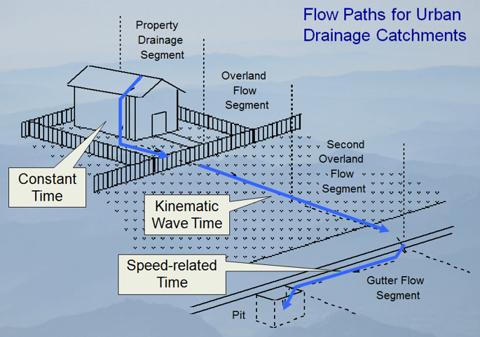
Flow paths for urban drainage catchments: rainfall is routed through a property drainage segment, one or more overland flow segments and a gutter flow segment to the pit, combining a constant time, kinematic wave time and speed-related time. Enter your own catchment geometry in the fields below.
Method: kinematic wave overland flow equations from Australian Rainfall & Runoff 1987 (ARR87). Current practice should be checked against Australian Rainfall & Runoff 2019 and current BOM design rainfall data.
Rational Method – Peak Design Flow
Estimates peak design discharge for a small catchment using the Rational Method, commonly applied to urban catchments up to a few hundred hectares.
Typical published runoff coefficient ranges: roofs & sealed pavement 0.80–0.95; roads 0.70–0.90; lawns & grassed areas 0.15–0.35; bushland/undeveloped 0.10–0.25. Composite catchments should use an area-weighted average C — confirm values against current ARR / local council guidance.
Formula: Q = C·I·A / 360 (Q in m³/s, C dimensionless, I in mm/h, A in hectares) — the standard Rational Method equation used in Australian drainage practice.
Manning’s Equation – Pipe & Channel Capacity
Estimates flow velocity and discharge capacity for a circular pipe or a trapezoidal/rectangular open channel using Manning’s equation.
Typical roughness n (AS/NZS 3500.3 Table 5.4.9): PE/PVC 0.009–0.010, smooth concrete 0.011–0.012, trowelled concrete 0.012–0.015, asphalt paving 0.013–0.015, brickwork 0.014–0.016, corrugated metal 0.012–0.015, earth-lined channels 0.018–0.025, rock lining/rip-rap 0.025–0.030, grassed/vegetated channels 0.025–0.075 (depending on growth).
Formula: V = (1/n)·R2/3·S1/2 (SI units, R in m, S as fraction); Q = V·A. Standard open-channel hydraulics (Manning, 1889; Chow, 1959); typical n values from AS/NZS 3500.3:2015 Table 5.4.9.
Stormwater Pipe Sizing (Colebrook–White)
Estimates the hydraulic capacity of a single circular site stormwater drain using the Colebrook–White equation, in accordance with AS/NZS 3500.3:2015 Clause 5.4.11 and the roughness values of Table 5.4.11.2. For a pipe network, check each pipe individually.
Method: Colebrook–White equation, general form using hydraulic radius, consistent with AS/NZS 3500.3:2015 Clause 5.4.11 and Table 5.4.11.2 (water at 20°C). Full-pipe velocity should not exceed 2.0 m/s (Clause 5.4.11.2); velocities of 1.5 m/s or less are recommended at pipe outlets to stormwater pits.
Downpipe & Eaves Gutter Sizing
Step 1 calculates the roof catchment area per downpipe (AS/NZS 3500.3 Clause 3.4). Step 2 looks up the minimum vertical downpipe size for a given eaves gutter effective cross-sectional area (Table 3.5.2).
Source: AS/NZS 3500.3:2015 Clause 3.4 (catchment area) and Table 3.5.2 (downpipe sizing). Table range: 3500–20 000 mm² for 1:500 and steeper; 4700–26 800 mm² for flatter than 1:500. Outside this range, individual engineering design is required.
Valley Gutter Design
Determines the minimum sheet width and effective dimensions of a valley gutter from the design rainfall intensity, per AS/NZS 3500.3 Table 3.6.2. Applies within the limitations of Clause 3.6.1: roof slopes not less than 1:4.5 (12.5°), nominal valley side angle 1:3.4 (16.5°), and catchment area not exceeding 20 m².
Source: AS/NZS 3500.3:2015 Table 3.6.2, derived from Martin and Tilley (1968). Freeboard (hf) 15 mm; sheet width allows for side rolls or bends of 25 mm. Table range: design rainfall intensity up to 400 mm/h — above this, individual engineering design is required.
Box Gutter & Spreader – Design Requirements
Box gutter, rainhead, sump and overflow device sizing in AS/NZS 3500.3 is read from a set of interrelated design graphs (Appendix I, Figures I1–I8), which cannot be reliably digitized as a calculator. This tool instead checks a proposed box gutter design against the Standard’s stated limitations (Clause 3.7). The sole width, depth, rainhead and overflow device dimensions themselves must be taken from AS/NZS 3500.3 Appendix I or determined by a suitably qualified hydraulics engineer.
Source: AS/NZS 3500.3:2015 Clause 3.7 (limitations, layout and overflow devices). This is a compliance check only, not a hydraulic capacity calculation.
Roof Spreaders
AS/NZS 3500.3 Clause 3.4.5 gives no capacity formula for spreaders (a device at the foot of a downpipe that distributes rainwater onto a roof at a lower level); a spreader is sized by the roof drainage system of the lower catchment taking the combined flow. The Standard requires, where a spreader is used:
- for a tiled roof, sarking at least 1800 mm wide on each side of the point of discharge, extended down to the eaves gutter in accordance with AS 2050; or
- for a corrugated metal roof, side laps sealed for the full length, for at least 1800 mm on each side of the point of discharge.
The downpipe and gutter system of the lower catchment must be sized (using the tools above) to take the total flow from both the upper and lower roof areas, and an increased overflow allowance should be considered for the lower gutter.